Although they may not seem as exciting as amps or effects, Input, Output, FX Loop, Split, and Merge blocks are integral to the sound and performance of your presets. Use these blocks to properly gain stage your levels, create parallel routings, incorporate your favorite external pedals, implement switchable alternate signal paths, and more. Refer to Signal Path Routing for additional details.

Input and Output blocks appear green to indicate a signal is present, and red if the signal is clipping (overloading). If clipping is indicated, reduce the signal level of your source instrument, the Input or Output block’s Trim or Level parameters, the effect and amp blocks' levels, or try adjusting the Global Settings > Ins/Outs options that affect levels for the Inputs and Outputs in use. Clipping should be avoided to keep your signal free of unwanted distortion.
Input Blocks
By default, all presets, even “empty” New Presets, include at least one Input block (at the left of Path 1A), but each preset can have up to four Input blocks (one each for Path 1A, 1B, 2A, and 2B).
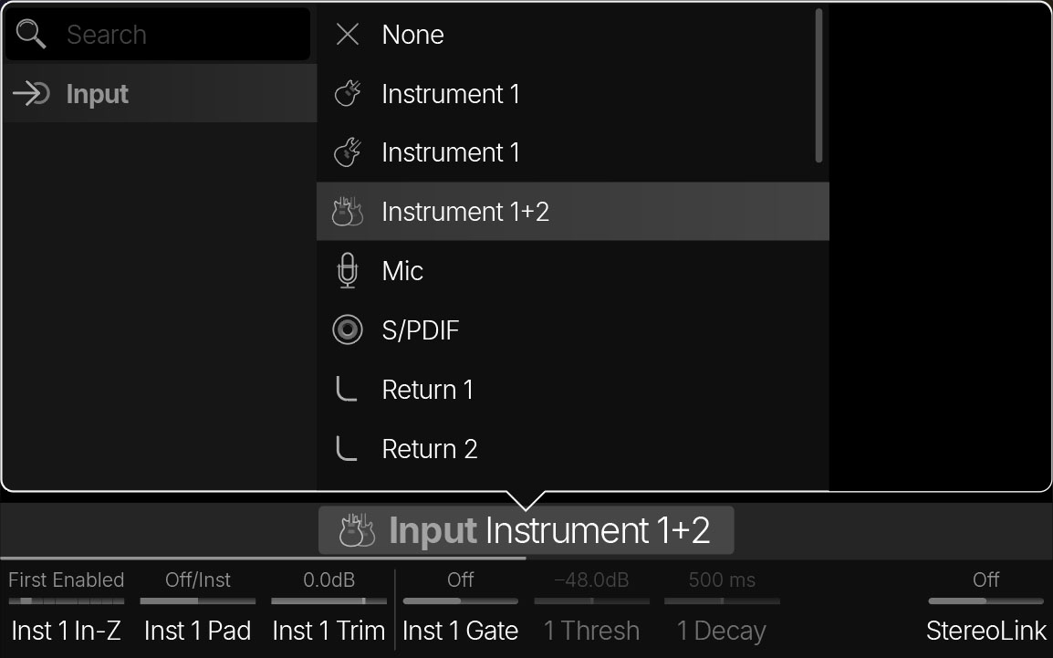
Selecting an Input
-
From the Home > Edit screen, tap an existing Input block

-
Alternatively, tap an empty Input block

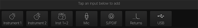
Tip: Within an empty New Preset, only the main Path 1A and Path 2A are shown. You can also create Paths 1B and 2B as parallel paths, each with its own Input block. See Serial vs. Parallel Path Routing.
|
Input |
Description |
|---|---|

None |
Disables (mutes) the input block on that path. |

|
Helix Stadium XL Instrument 1+2 receives the signal from both jacks simultaneously. Note that Instrument 1+2 offers independent parameters, which allow you to connect either two separate instruments or to enable StereoLink for connecting one stereo instrument. |

Mic |
Receives the signal from the XLR Mic In jack. Overall mic gain is adjusted from Global Settings > Ins/Outs > Mic In Gain. Note: 48V phantom power may be required for some studio microphones and can be enabled from Global Settings > Ins/Outs > Mic In Phantom. |

S/PDIF |
Receives the signal from the stereo S/PDIF digital input, where you can connect the S/PDIF output from external gear to route its digital signal into Helix Stadium. NOTE: Only one digital Input can be used in a preset at the same time. |

Return 1, Return 2, Return 1-2 |
Returns 1 and 2 (and with Stadium XL Note: Returns 1/2 (Helix Stadium) or Returns 3/4 (Helix Stadium XL |

USB 3/4, USB 5/6, USB 7/8 |
USB inputs 3/4, 5/6, and 7/8 can all be used for stereo USB audio inputs for your connected computer’s DAW software. See USB Audio. Helix Stadium also receives input from USB 1/2, but it’s dedicated to monitoring stereo USB audio from your computer, with the USB 1/2 input unprocessed by any of the current preset’s processing blocks. As such, USB 1/2 is not available as a selectable Input block source. |
Input Parameters
Note: Also see the Global Settings > Ins/Outs section for additional parameters.
Input > Instrument [X]
Click here to view Input > Instrument [X] settings...
Note: Helix Stadium XL has Instrument 1 and Instrument 2 inputs, where Helix Stadium has a single Instrument input. Therefore, parameter names differ slightly between the two.
|
Parameter |
Description |
|---|---|
|
Inst [X] Input Z |
Helix Stadium has an impedance circuit on its Instrument Input(s) that affects tone and feel by loading your guitar or bass’s pickups as they would by an effect pedal or amplifier. When set to First Block, the circuit reflects the impedance of the first block, regardless of whether it’s enabled or bypassed. When set to First Enabled, the impedance circuit reflects the impedance of the first enabled block on the path. Or choose a fixed impedance from 10k Ohm to 1M Ohm. A lower value typically results in some high frequency attenuation, lower gain, and an overall “softer” feel. A higher value provides full frequency response, higher gain, and an overall “tighter” feel. |
|
Inst [X] Pad |
Set to Off/Inst for most guitars, basses, or other instruments. Set to On/Line for guitars or basses with very hot active pickups or line level devices such as keyboards, synths, and drum machines. There’s really no rule here; use what sounds best. Note: Global Settings > Ins/Outs > Instrument In [X] Pad settings can globally override all Input blocks' Pad settings. |
|
Inst [X] Trim |
Sets the Instrument [X] digital input level and is used to compensate for overly soft or loud instruments. Important! Setting Trim to a value higher (or lower) than 0.0 dB effectively boosts (or attenuates) your signal into the first block, which may result in a less than accurate response. |
|
Inst [X] Gate |
Turns the Input block’s built-in noise gate on and off. |
|
1 Thresh |
Sets the noise gate’s Threshold. The gate “opens” when the signal’s level exceeds the Threshold, allowing audio to pass through. The gate “closes” when the signal’s level drops below the Threshold. Adjust Threshold so that only softer, unwanted signals (such as noise or hum) are gated. |
|
1 Decay |
Controls the length of time it takes for the open noise gate to close once the signal drops below the Threshold. Increase Decay if you want the gate to gradually lower the signal instead of chopping it off abruptly. |
|
StereoLink |
Helix Stadium XL When On, all Instrument 2 parameters are grayed out and their values echo those of the equivalent Instrument 1 parameters. Instrument 1 is routed hard left, and Instrument 2 is routed hard right. |
Input > Mic
Input > Return, S/PDIF, and USB
Output Blocks
Each preset can have up to four Output blocks (one each for Path 1A, 1B, 2A, and 2B).
By default, Output blocks are set to Matrix (1/4”, XLR, Phones), which means paths are routed to Helix Stadium’s Matrix Mixer, where they can be mixed differently for the 1/4”, XLR, and Phones outputs. Alternatively, they can be routed directly to a single stereo output (including 1/4”, XLR, or Phones), bypassing the Matrix Mixer.
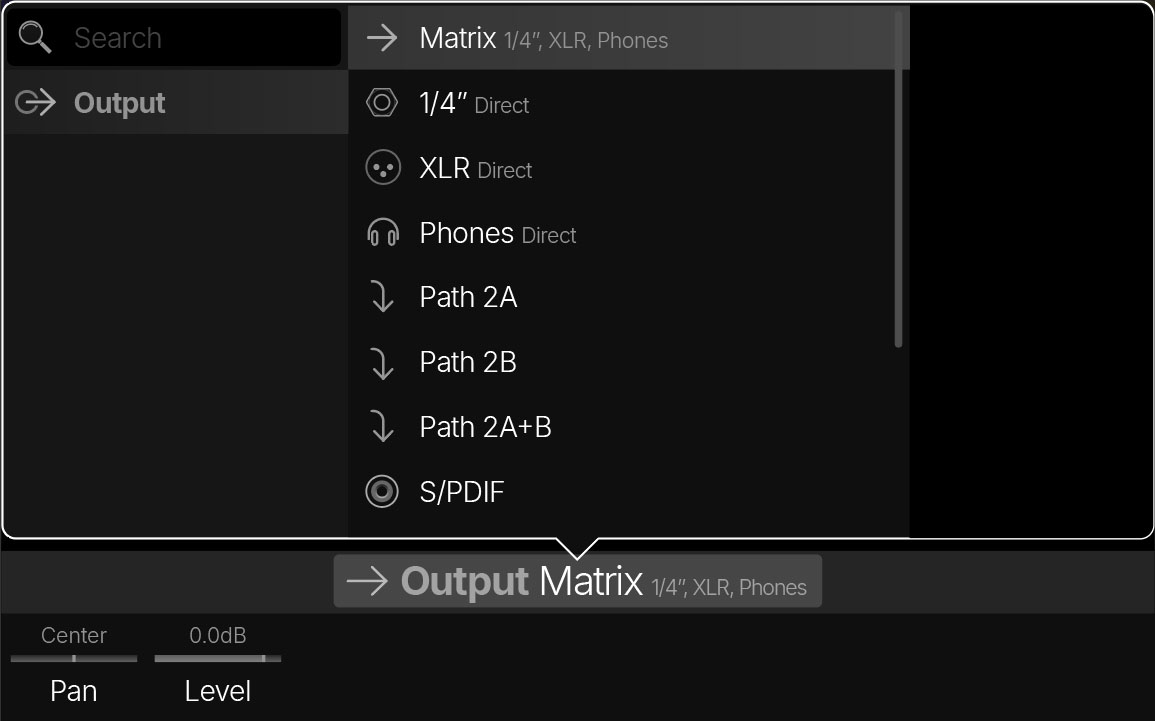
Selecting an Output
-
From the Home screen, tap an Output block. The Output appears in the inspector. Turn the Lower Knob to change the Output.
-
Alternatively, tap its name in the inspector header to open the Output List (see below).
Tip: With an empty New Preset, only the main Path 1A and Path 2A are shown. You can also create Paths 1B and 2B as parallel paths, each with its own Output block. See Serial vs. Parallel Path Routing.
|
Output |
Description |
|---|---|

Matrix (1/4”, XLR, Phones) |
The path is sent to the Matrix Mixer, where it can be mixed independently for the 1/4”, XLR, and Phones outputs. Even if you don’t use the Matrix Mixer, this is still the best option, as it lets you hear the path through all three main outputs simultaneously. The Output blocks of all Factory Presets (and most Preset Templates) are set to Matrix (1/4”, XLR, Phones) by default. |

1/4" Direct |
The path is routed directly to the 1/4” outputs, bypassing the Matrix Mixer entirely. |

XLR Direct |
The path is routed directly to the XLR outputs, bypassing the Matrix Mixer entirely. |

Phones Direct |
The path is routed directly to the Phones output, bypassing the Matrix Mixer entirely. |

Path 2A, 2B, or 2A+B |
These Outputs only appear for Path 1A and Path 1B Output blocks and are used to route Path 1 into Path 2. This type of “serial” routing provides an extended signal path where more blocks can be added. See Serial vs. Parallel Path Routing. |
|
S/PDIF |
If Global Settings > Ins/Outs > S/DPIF Out is set to “Direct Out,” the Output is routed directly to the S/PDIF digital output. However, the S/PDIF Out can also be set to reflect the Matrix Mixer’s 1/4”, XLR, or Phones output. Its output level and sample rate can also be set from Global Settings > Ins/Outs > S/PDIF Out Level and S/PDIF Sample Rate. |

Send 1/2 |
The path is routed directly to Send 1/2 (and/or on Helix Stadium XL |
|
USB 1/2, USB 3/4, USB 5/6 |
The path is routed directly out USB 1/2, 3/4, or 5/6 in stereo, for routing signals to your computer or mobile devices. USB Outs 7 and 8 are dedicated for DI recording output, and are not available as an Output block. See USB Audio. |
Output Parameters
Note: Also see the Global Settings > Ins/Outs section for additional parameters.
Split and Merge Blocks
Split and Merge blocks can be added to create parallel or dual paths, which can be very useful for isolating specific effects, creating alternate switchable routings, and more. See Serial vs. Parallel Path Routing.
All paths are stereo. When a Split block is added, it splits the signal into Path A and Path B in parallel. When a Merge > Mixer block is added, it mixes Path B back into Path A.
Note: The overall output level of the signal is increased slightly for each parallel path added. Adjust the Level parameter in the Merge > Mixer block for the desired output level.

Adding a Split Block
-
Tap an empty area on Path 1A or Path 2A.
-
Tap Split on the left side of the inspector header. A Split > Y block is added, and a Path B is created with its own Output block. Alternatively, drag an existing Amp, Cab, or Effect block down slightly, and it’ll be added to a new parallel path B connecting to Path A with Split > Y and Merge blocks.
-
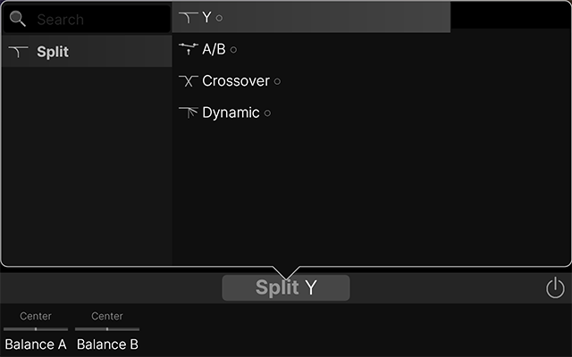
To change the type of Split, turn the Lower Knob or tap the inspector header to open the Split List (see below):
-
Adding a Split to the left of an existing Merge block on path A automatically joins the existing parallel path.
-
Multiple Split and Merge > Mixer blocks can be added to Path A for several parallel paths, one after the other. For example, say you want the signal to split into parallel Amp blocks, merge into a dual Cab block, and later, split into parallel Delay and Reverb blocks, and then merge again before the Output. There’s a lot of flexibility here.
-
To create a Path B Input block, drag the Split down to Path B—or—clear the Split by swiping it off the screen.
Split > Y
Adding a Split block adds a Split > Y by default. With a Split > Y block, the stereo input signal is sent to stereo Paths A (upper) and B (lower) evenly, but the Balance A and Balance B parameters can be used to separate the incoming signal into separate left (to Path A) and right (to Path B) channels.
|
Parameter |
Description |
|---|---|
|
Balance A |
Adjusts the stereo balance (pan) of the signal sent to Path A (upper) and Path B (lower). To split the signal into separate left and right channels, set Balance A to Left 100 and Balance B to Right 100. |
|
Balance B |

Split > A/B
Split > A/B allows for tactile control over which path your signal is routed to—Path A (upper) or Path B (lower).
|
Parameter |
Description |
|---|---|
|
Route To |
Determines the amount of the signal sent to Path A (upper) vs. Path B (lower). When set to “Even Split,” the signal is split evenly between the two stereo paths. Tip: Assign this parameter to a Stomp switch to create an A/B toggle switch, where each press switches between the two paths. Alternatively, assign this parameter to an expression pedal (or MIDI CC) to blend between Paths A and B. See Learn Controller. |

Split > Crossover
Split > Crossover splits the incoming signal by frequency, letting you process the high and low frequencies independently. This is especially useful with electric bass, where distortion may be applied only to the high frequencies, allowing the non-distorted low frequencies to pass through.
|
Parameter |
Description |
|---|---|
|
Frequency |
Determines the crossover point at which your signal is split into high and low frequencies. Any signal above this frequency is sent to Path A (upper); any signal below this frequency is sent to Path B (lower). |
|
Reverse |
When On, reverses the path assignments (any signal above the crossover frequency is sent to Path B, any signal below the crossover frequency is sent to Path A). |

Split > Dynamic
Split > Dynamic lets you route your signal based on input level or even your playing dynamics. For example, if Path A has Delay and Reverb blocks and Path B has a Distortion, playing softly (or rolling your guitar’s volume knob back) will apply more Delay and Reverb, whereas playing harder (or rolling your guitar’s volume knob up) will lower the Delay and Reverb and add Distortion.
|
Parameter |
Description |
|---|---|
|
Threshold |
Determines the signal level above which gets routed to Path B. Playing softer (signal below the Threshold) is routed to Path A; playing louder (signal above the Threshold) is routed to Path B. |
|
Attack |
Determines how quickly the signal is routed to Path B once reaching the Threshold. |
|
Decay |
Determines how quickly the signal returns to Path A once it falls below the Threshold. |
|
Reverse |
When On, reverses the path assignments (any signal above the Threshold value is sent to Path B, any signal below the Threshold value is sent to Path A). |

Adding a Merge Block
The primary purpose of a Merge block is to place it after a Split block to rejoin and mix the Path B signal back with Path A.
-
Tap an empty area on Path 1A or Path 2A.
-
Tap Merge on the right side of the inspector header. A Merge block is added, and a Path B is created with its own Input block (provided a Split block hasn’t already been added to the Merge’s left). Alternatively, drag an existing Amp, Cab, or Effect block down slightly, and it’ll be added to a new parallel path B connecting to Path A with Split > Y and Merge blocks.
-
Adding a Merge to the right of an existing Split block on path A automatically joins the existing parallel path.
-
Multiple Split and Merge > Mixer blocks can be added to Path A for several parallel paths, one after the other. For example, say you want the signal to split into parallel Amp blocks, merge into a dual Cab block, and later, split into parallel Delay and Reverb blocks, and then merge again before the Output. There’s a lot of flexibility here.
-
To create a Path B Output block, drag the Merge down to Path B—or—clear the Merge by swiping it off the screen.
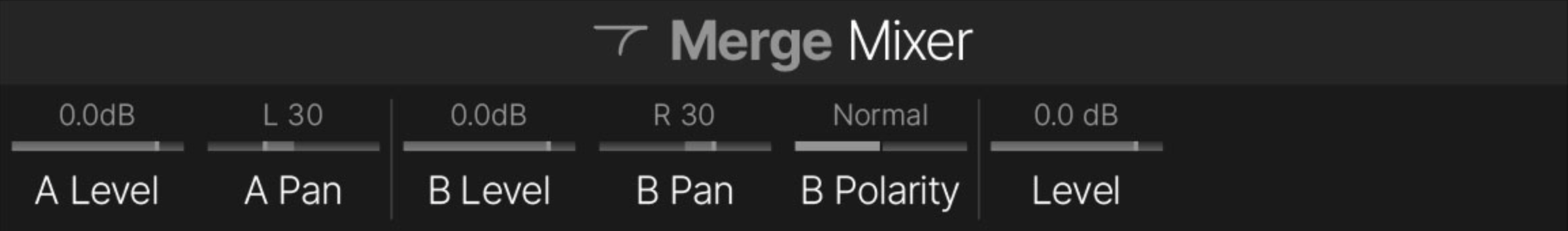
Merge > Mixer
|
Parameter |
Description |
|---|---|
|
A Level |
Adjusts the output level of Path A (upper). |
|
A Pan |
Adjusts the left/right stereo balance of Path A (upper). When set to Left 100, only the left signal is passed through; when set to Right 100, only the right signal is passed through. |
|
B Level |
Adjusts the output level of Path B (lower). |
|
B Pan |
Adjusts the left/right stereo balance of Path B (lower). When set to Left 100, only the left signal is passed through; when set to Right 100, only the right signal is passed through. |
|
B Polarity |
Inverts the polarity of Path B. Typically, this should be set to “Normal.” |
|
Level |
Adjusts the overall output level of the Merge block. |
FX Loop, Send, and Return Blocks
An FX Loop block combines a Send and Return (either mono or stereo) to let you patch your favorite external effects pedals (or rack gear) into your preset’s signal flow. The FX Loop block category also has separate Send and Return blocks (mono or stereo) that let you route out to—or in from—external gear in the middle of a signal path.
Note: Multiple instances of the same Send can be used more than once in a preset. However, only one instance of the same FX Loop or Return can be used in a preset.
Note: Returns 1/2 (Helix Stadium) or Returns 3/4 (Helix Stadium XL ![]()
Clip Indicator
FX Loop and Return blocks turn red if their input signal is too high, at which point you should reduce the level of the preceding Stadium blocks and/or external gear to avoid clipping.


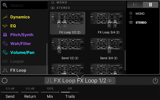
Adding an FX Loop Block
-
From the Home > Edit screen, tap an empty area on a path where you want to add an FX Loop block. Categories appear in the inspector.
-
Press [>] (or swipe the category buttons) and tap the FX Loop category button. The Model List opens (see below).
-
Tap the desired item to load it. Alternatively, double-tap the desired item to load it and close the Model List.
Note: The FX Loops' input and output level can be changed globally from Global Settings > Ins/Outs > FX Loop [X] Level. An FX Loop block’s Send and Return level can further be adjusted individually within your preset using the FX Loop’s Send and Return parameters, as shown in the following tables.
FX Loop > FX Loop
|
Parameter |
Description |
|---|---|
|
Send |
Adjusts the level of the FX Loop’s Send output(s). 0.0 dB is unity gain. |
|
Return |
Adjusts the level of the FX Loop’s Return input(s). 0.0 dB is unity gain. |
|
Mix |
Blends the FX Loop signal vs. the dry signal passed through the FX Loop block. When set to 0%, the path bypasses the FX Loop completely. When set to 100%, the entire signal is fed through the FX Loop, and no dry-through signal is heard. (This means that if you don’t currently have your external gear connected to the Send & Return jacks, you won’t hear any output signal unless you bypass the FX Loop block!) When connecting time-based pedals like delays or reverbs, it’s best to leave the pedal’s Mix at 100% and control the amount of the pedal’s effect from the FX Loop block’s Mix knob. This helps minimize phase issues and latency. For pedals like distortion, fuzz, or compression, it’s common to keep the FX Loop block’s Mix knob at 100%, but lowering this value can sometimes provide cool parallel effect sounds. |
|
Trails |
When Off, the return signal from any external gear is instantly muted when the FX Loop block is bypassed. When On, the return signal continues to decay naturally when the block is bypassed or a different snapshot is selected. |
FX Loop > Send
|
Parameter |
Description |
|---|---|
|
Send |
Adjusts the level of the Send’s output(s). 0.0 dB is unity gain. |
|
Dry Thru |
Adjusts the level of the dry (unaffected) signal passed through the Send block, independent of the Knob 1 (Send) level. Normally, this should be set to 0.0dB, but when set to -120.0 dB, the Send block can act as an A/B switch, toggling between sending signal to the external device (block enabled) and sending signal through to the next block (block bypassed). |
FX Loop > Return
|
Parameter |
Description |
|---|---|
|
Return |
Adjusts the level of the Return’s input(s). 0.0 dB is unity gain. |
|
Mix |
Adjusts the balance between the Return signal and the dry signal passed through the Return block. When set to 0%, the path bypasses the Return completely. When set to 100%, the entire signal is fed from the Return, and no dry signal is heard. |